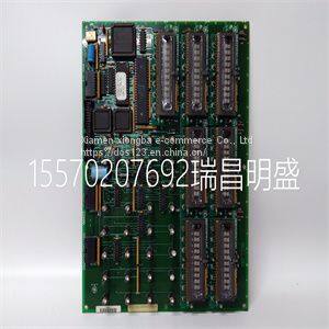
Module spare parts DS215KLDBG1AZZ03A DS200KLDBG1ABC
Product Details
Product Details
Product Description
Product DescriptionFocus on DCS, PLC, robot control system and large servo system.
Main products: various modules / cards, controllers, touch screens, servo drivers.
Advantages: supply of imported original products, professional production parts,
Fast delivery, accurate delivery time,
The main brands include ABB Bailey, Ge / fuanc, Foxboro, Invensys Triconex, Bently, A-B Rockwell, Emerson, ovation, Motorola, xyvom, Honeywell, Rexroth, KUKA, Ni, Deif, Yokogawa, Woodward, Ryan, Schneider, Yaskawa, Moog, prosoft and other brands
| DS215KLDBG1AZZ03A DS200KLDBG1ABC |
>> Copper Wire Iron Steel Crusher Rubber Scrap Tyre Recycling Equipment Tire Shredder Machine Prices
>> High-Quality Tube Welding Machine for Efficient Production Processes
>> Aluminum Solar Panel Carport Mounting PV System Carport Mounting Solar
>> Manual Sliding Doors Semi Sliding Door Closer
>> New Design Cheap Best Mobility Scooter Folding Best Electric Scooter Electric Scooter for Adults
>> Hot Sale Plain Socks Knitting Machine
>> Hand Tool - Extension Pole
>> Creality K1c 3D Printer 600mm/S Auto Leveling Robust Direct Extruder Tri-High Speed Printing Upgrade K1 with Ai Camera Printer
>> Commercial Indoor Upright Sports Body Building Home Gym Spin Bicycle Fitness Equipment Stationary Cycling Trainer Air Magnetic Exercise Spinning Bike
>> Various Styles Sanitary Class Vacuum Reactor
>> Factory Wholesale Communication Long Range RF Lora Wireless Receiver
>> Animal Machine Pellet Plant Production Line Mixer Poultry Feed Pelletizer Line
>> Small Crawler Agricultural Tractor Diesel Power Tiller
>> Eco-Friendly Reliable Manufacturer Aire Acondicionado 9000 Btu
>> 6W 8W 10W 12W 15W COB Commercial Lighting Recessed Ceiling LED Spot Down Light
>> Disc Blade Disc Plough Blades Harrow Disc Blade
>> High Quality Apple Peel Extract Bulk Phlorizin Powder CAS 60-81-1 Phlorizin
>> Customized 150cm Stainless Steel Pig Water Trough /Feeder
>> Variety of Styles of Food Tricycle Hot Dog Barbecue Truck
>> CMP 90hx Graphic Cards GPU Video Card Gaming Card GPU Rig for GPU CMP 90hx 50hx 170hx
>> Wood/ Metal/ Rubber/ Plastic/ Cardboard Shredder Machine Chamber Box Knife Blade
>> Upgrade to LEXUS ES350 2018 auto car accessories bodykit body kit the front bumper sets for LEXUS ES200 ES250 ES300h 2013-2017
>> new trends 2021 design casement inswing door and window Aluminum Glass Windows
>> Gtwy Series 16m Battery Drive Double Mast Vertical Boom Lift Platform
>> Ck6132 CNC Lathe CNC Milling Machine
>> Rechargeable Backup Power Battery Portable Power Station
>> 4K HDMI Cable Male to Male OEM ODM HDMI 2.0 Cable 3D 16gbps 4K60Hz Gold Plated Video HDMI Cable with Ethernet
>> Wholesale Cylindrical Motorcycles Tax Disc Holder
>> home use movable wheat and rice thresher in stock
>> Three Color Outdoor Crossbody Shoulder Bag for Men Women′s