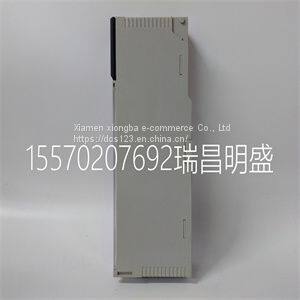
Module spare parts PTQ-PDPMV1
Product Details
Product Details
Product Description
Product DescriptionFocus on DCS, PLC, robot control system and large servo system.
Main products: various modules / cards, controllers, touch screens, servo drivers.
Advantages: supply of imported original products, professional production parts,
Fast delivery, accurate delivery time,
The main brands include ABB Bailey, Ge / fuanc, Foxboro, Invensys Triconex, Bently, A-B Rockwell, Emerson, ovation, Motorola, xyvom, Honeywell, Rexroth, KUKA, Ni, Deif, Yokogawa, Woodward, Ryan, Schneider, Yaskawa, Moog, prosoft and other brands
| PTQ-PDPMV1 |
>> Premium Automatic Mixing Equipment for Edible Mushroom Production
>> Sesame Coffee Plam Paddy Carob Rice Bean Seed Destoner Machine
>> 15mm Wholesale Silvery Aluminum Fine Mist Spray Pump Easy Perfume Bottle Mist Sprayer Pump
>> Round Base 360 Photobooth Selfie Spinner Camera Ipadselfie Rotating Automatic for Party
>> Yyc China CNC Non Woven Geotextile Fabric Layer Auto Cutter Cutting Machine
>> Stainless steel Gun Shaped Folding pocket survival knife
>> High Speed EDM Erosion Molybdenum Wire Cutting Machine Dk7763
>> Car mudguard for a21 chery a5 cowin Auto parts black fender
>> Aokol -35c Low Temp 15kw Air Water Heat Pump, R32 WiFi Controll Heat Pump, European Market Floor Heating Central Air Conditioning with CE RoHS.
>> Smart Micro LED Projector with WiFi for Movies and Presentations
>> Quarts Crushing Machine Smooth Toothed Roller Crusher Sand Making Roller Crusher For Brittle Material Fine Crushing Machine
>> Factory Direct Sales Multifunction 0.8 Ton Mini Excavator 1 Ton Excavator
>> Fiberglass FRP Plastic Grating FRP fiberglass Checker Plate
>> Children Sliding Car with Musical Early Education Music
>> korea high tecnolgy 4515 fishing rod quality customize fishing rod bag hard rod
>> 102HP 2.4m Cutter Rice Combine Harvester, Rubber Track 550*90*56
>> Gsl Energy North American High Frequency Max 15kVA PV Input Split Phase 2/3 Phase MPPT Solar Hybrid Inverter 12kw
>> waste tire recycling rubber powder machine
>> Qh Pack High Speed Corrugated Cardboard Production Line Making Machinery
>> Direct Reading Water Tank Level Gauge Liquild Level Indicator
>> Precision Plate Shear Cutter for Latin America
>> Hydraulic Plane Grinder Machine My1022 My1024 My1230 Automatic Metal Plane Polish Machine
>> Balcony Sunroom Design Golden Supplier Aluminium Sunroom Modern Glass House For Sale
>> Industrial Conveyor Belt Metal Detection Weight Detection All-in-One Machine Food Meat Nut Beverage Metal Detector for Processing Line
>> Poulty Egg Incubator Adding Water System PP Material Water Tank
>> Cbr Cross Head Double Speed Position Limit Switch for Crane Travelling European Type Hoist Stop
>> Exclusive Range of Nickle Fitting Chairman Lining Material Fashion Style Genuine Leather Key Case Manufacturer
>> Ra Electric Automatic Screw Fastening Assembly Machine with Auto Feeder
>> Timing Kit for Dodge with OE No 4740275 4448154 04778707AB TK1135 for CHRYSLER 3.8L
>> Professional Quality Control Team Plastic Pallet Mold Injection Machine for Sale