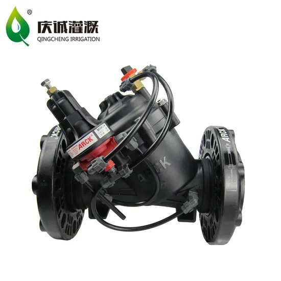
Arck 4" Plastic Solenoid Valve Hydraulic Control Valve with Flange
Basic Info.
Model NO.
MV100F
Standard
Standard
Connection Mode
Flange
Power
Hydraulic
Material
Plastic
Type
Self-Operated
Connection Sizes
4"
Model
Mv100f
Color
Black
Weight
6kg
Working Pressure
0.35-10.0 Bar
After Sales Period
1 Year
Transport Package
Sea Transportation
Specification
35.5x33x41.5 cm
Trademark
ARCK
Origin
China Fuzhou
Product Description
FEATURE & ADVANTAGE•Diaphragm hydraulic control valve, driven by system pressure,electrical signal control on/off.
•With internal water inlet and outlet circuit. An internal filter unit makes the valve self-cleaning.
•Engineered Plastic Valve with Industrial Grade Design. Highly durable, chemical & cavitation resistant.
•Y-shaped valve body design, large overflow and small head loss.
•Unitized Flexible Super Travel Diaphragm with a Guided Plug.Accurate and stable regulation with smooth closing.
•The external pressure pipeline design can be easily checked and maintained online.
TECHNICAL DATA
•Body design and optional size: 1½″- 6″; DN40-DN150
•Optional connection port:
•Thread connection: Internal thread BSP.T/NPT ( 1½″, 2″, 3″; DN40, DN50, DN80 )
•Flange connection: 3″, 4″, 5″, 6″
•Clamp type interface: 2″or 3″plastic groove adapter interface
•Pressure rating: 10bar; 150psi
•Operating temperature: not higher than 60ºC; 140ºF
•Material:
•Body, bonnet, valve core: glass fiber reinforced nylon
•Diaphragm: Rubber
•Spring: stainless steel
•Sealing gasket: rubber
•Bonnet bolts: Stainless steel
Main Valve Dimensions & Specifications
| picture | ||||||||
| Sizes | Inch | 1½″(Dn40) | 2″(Dn50) | 3″(Dn80) | 3″(Dn80) | 4″(Dn100) | 5″ (Dn125) | 6″(Dn150) |
| DN | ||||||||
| End Connections | Internal Thread BSP.T/NPT | Internal Thread BSP.T/NPT | Internal Thread BSP.T/NPT | Plastic Flanges | Plastic Flanges | Plastic Flanges | Plastic Flanges | |
| L(mm) | 228 | 232 | 298 | 314 | 342 | 440 | 440 | |
| H(mm) | 146 | 168 | 180 | 224 | 296 | 370 | 388 | |
| h(mm) | 41 | 43 | 55 | 98 | 113 | 129 | 145 | |
Flow Properties
| Sizes | 1½″(Dn40) | 2″(Dn50) | 3″(Dn80) | 4″(Dn100) | 5″ (Dn125) | 6″(Dn150) |
| KV (m3/h@ ΔP of 1bar) | 50 | 100 | 100 | 200 | 340 | 340 |
MANUAL CONTROL VALVE
• The manual control valve is composed of the main valve and the three-way manual control valve. Powered by water with manual control on/off.
• Optional size:1.5″(Dn40),2″(Dn50),3″ (Dn80),4″(Dn100),5″(Dn125),6″(Dn150)
• Connection method: internal thread/flange
| MODEL & TECHNICAL DATA | ||||||
| Model | Connection Sizes | Connections | Working Pressure (bar) | Voltage (V) | Carton Size (cm) | Weights (kg) |
| MV040B | 1½″ (Dn40) | internal thread BSP/NPT | 0.35-10.0 | 24V AC or DC or 12-24V DC pulsed | 31×24×26.5 | 2 |
| MV050B | 2″ (Dn50) | internal thread BSP/NPT | 0.35-10.0 | 24V AC or DC or 12-24V DC pulsed | 31×24×26.5 | 2 |
| MV080B | 3″ (Dn80) | internal thread BSP/NPT | 0.35-10.0 | 24V AC or DC or 12-24V DC pulsed | 32×29.5×24 | 3 |
| MV080F | 3″ (Dn80) | flange | 0.35-10.0 | 24V AC or DC or 12-24V DC pulsed | 32×29.5×24 | 4 |
| MV100F | 4″ (Dn100) | flange | 0.35-10.0 | 24V AC or DC or 12-24V DC pulsed | 35.5×X33×41.5 | 6 |
| MV125F | 5″ (Dn125) | flange | 0.35-10.0 | 24V AC or DC or 12-24V DC pulsed | 50×35×50 | 10 |
| MV150F | 6″ (Dn150) | flange | 0.35-10.0 | 24V AC or DC or 12-24V DC pulsed | 50×35×50 | 11 |
>> New Release Small Grain Peeling Machine/Energy Saving Maize Harvest Thresher/Long Service Life Corn Husker Peeler
>> OEM Custom Made PVC Plastic Product Plastic Part Cattle Foot Ring
>> Ice Feeling Mint Silk Nylon Spandex Polo Shirt for Ultimate Comfort
>> Sandy Soil Peanut Harvester Designed for Unique Farming Conditions
>> TK1028-10 ENGINE TIMING CHAIN KIT OE 2669970094 6600500111 for SMART OM 660
>> 4*8 1-30mm Colored Factory-Price PVC Foam Board
>> Strong Operating Pressure High-Pressure Equipment Single-Arm Low-Temperature Chemical Marine Loading and Unloading Arm Machine with Swivel Joint
>> Zipper Stand Up Pouch Filling Nitrogen Sealing Premade Bag Freeze Dried Fruit Doypack Packing Machine
>> Best Price High Speed HDMI Cable with Ethernet 8K
>> ASTM D1598 Pipe Hydrostatic Pressure Tester
>> Sheet Metal Plate and Pipe CNC Fiber Laser Cutting Machine for Stainless Steel Tube 1530
>> Milling Farm Machinery Maize Grinding Corn Hammer Mill Grinder
>> Electronic Timer Digital Concrete Plant Portable Concrete Batching Plant Ready Mix
>> Juice Carbonated Soft Soda Drinking Pure Water Filling Packaging Machine
>> Genuine Car Accessories 20-21 For Benz GLS X167 Upgrade MBH 20-21 Front Bumper Car Grille Flog Lamp Grille Wheel Arch Body Kits
>> Log Loading Crane Hydraulic Rotator 4 Ton Hydraulic Rotator Gr40A/F on Log Trailer Rotator
>> Wrap Dispenser with Cutter and Label Plastic Wrap Aluminum Foil and Wax Paper Dispenser for Kitchen Drawer Bamboo Roll Organizer
>> Turbocharger He451ve 2882111 3773562 for Isx Engine
>> Bull Block Aluminium Rod Straight Line wire drawing machine
>> Wholesale Factory Price Reusable Ecological Custom Logo Non Woven Tote Bag Colorful Shopping Recyclable Tote Non-Woven Bag
>> Economic Flat Metal Surface Grinding Machine High Precision Surface Grinder
>> 99% Purity CAS 90045-23-1 Garcinia Combogia Extract Cambogia Combogia Powder Garcinia Combogia
>> 25kg 20kg 50kg Multiwall Kraft Paper Valve Bag Sack for Cement Clay Gypsum Plaster Mortar Powder
>> High Speed Full Automatic Single Stage Plastic Bottle Blowing Machine Injection Stretch Blow Molding Machine
>> Chinese Manufacturers Full Automatic Construction Material Gypsum Board Making Machine Production Line
>> Plastic Injection Mould for 120L Large Outdoor Trash Can Dustbin Mold
>> Tractor Mounted Potato Harvester Machinery/Automatic Potato Receiving Machine 4uds-90
>> Tire Recycling Machine/Rubber Tire Shredder Scrap/Tire Shredding and Recycling Production Line
>> custom your own logo print mma gloves
>> 1ml 2.25ml 3ml 5ml Disposable Injection Medical Glass Prefilled Syringe