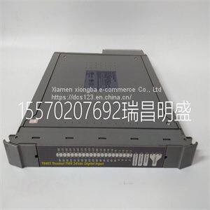
Module spare parts T8403
Product Details
Product Details
Product Description
Product DescriptionFocus on DCS, PLC, robot control system and large servo system.
Main products: various modules / cards, controllers, touch screens, servo drivers.
Advantages: supply of imported original products, professional production parts,
Fast delivery, accurate delivery time,
The main brands include ABB Bailey, Ge / fuanc, Foxboro, Invensys Triconex, Bently, A-B Rockwell, Emerson, ovation, Motorola, xyvom, Honeywell, Rexroth, KUKA, Ni, Deif, Yokogawa, Woodward, Ryan, Schneider, Yaskawa, Moog, prosoft and other brands
| T8403 |
>> AS2047 Australia standard bulletproof security aluminum glass bifold door for exterior commercial
>> Automated CNC Peeling Machine Production Line
>> Hot Sale Large Black Speckled Kidney Beans
>> Tiffany Table Lamp E27 Baroque Bedroom Beside Rustic Table Lamp (WH-TTB-56)
>> Leading-Edge dB-6146 Series Turret CNC Lathe - Delivering Precision and Versatility for a Wide Range of Applications
>> New Condition RO+EDI System Ultra-Pure Water Treatment Equipment Used for Equipment Electronic Semiconductor Use Water
>> PVC modern white frame folding door aluminum alloy glass folding door sliding door
>> N10 DC reduction motor Short gearbox motor Customs intelligent lock motor
>> Glue Dispersion Stirring Emulsification Reactor Stainless Steel Condensing Stirring Tank
>> Wholesale VIP Plastic Folding Stadium Auditorium Church Cinema Seating FRP Armchair Chair
>> Price Competitive Manufactuer CAT6 LAN Cable 350 MHz Computer Data Cable
>> Two Head Multi-Color Computerized High Quality Embroidery Machine
>> CE Approved Industrial Power Supply Energy Panel off Grid Solar Container System Ess-1mwh
>> 2022 factory supply tomato orange strawberry onion apple carrot sorting machine grading machine
>> Pulverizer Machine Philippines Glitter Pulver Purple
>> 4015 CNC Laser Machine for Precision Metal Cutting Efficiency
>> Modern carpets flooring carpet sofa living room carpet
>> Air Shipping Logistics Forwarder From China to Bratislava, Kosice, Poprad Tatra, Slovakia
>> Customizable Melamine Conference Table for Office Collaboration Spaces
>> 800/900/2100/2300/2600MHz Patch Adhesive LTE Antenna, 3 Meters RG174 Cable Fakra Connector Compatible with 3G 2G 4G Antenna
>> No MOQ Promotion 2D/3D Rubber Soft PVC Items for Gift
>> Eyebrow Pencil Rotating Positioning Laser Marking and Sorting Machine for Any Circular Product
>> Extra Soft and High-Temperature Resistant 200 Degree Single Core 26AWG 24AWG 22AWG 12AWG 10AWG 24AWG Silicone Wire Red/Black Heat-Resistant Wire
>> Violin Salzburg and Mozart Resin Fridge Magnet
>> High Quality Foam Machine Horizontal Styrofoam Cutters Hot Wire Continuous Foam Cutter mattress Cutting Machine
>> 99450797 Camshaft Position Sensor for Trucks
>> Xj250 Xj350 Xj450/Xj550 Xj650 Xj750 Workover Rig Oil Drilling Rig Truck Mounted
>> High Surface Hardness and Wear Resistance PCD Profile Cutters Tools for Click Slotting Machine
>> Ifak Mobile Pouch Emergency Backpack and Safety Individual Medical First Aid Kit Outdoor
>> 350/500ml Double Wall Stainless Steel Vacuum Insulated Tea Bottle with Custom Logo and Painting