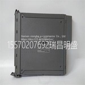
Module spare parts T8231
Product Details
Product Details
Product Description
Product DescriptionFocus on DCS, PLC, robot control system and large servo system.
Main products: various modules / cards, controllers, touch screens, servo drivers.
Advantages: supply of imported original products, professional production parts,
Fast delivery, accurate delivery time,
The main brands include ABB Bailey, Ge / fuanc, Foxboro, Invensys Triconex, Bently, A-B Rockwell, Emerson, ovation, Motorola, xyvom, Honeywell, Rexroth, KUKA, Ni, Deif, Yokogawa, Woodward, Ryan, Schneider, Yaskawa, Moog, prosoft and other brands
| T8231 |
This chapter describes input and output signal connections to the SCXI-1141/1142/1143 module through the front and rear signal connectors. Caution Connections that exceed any of the maximum ratings of input or output signals on the SCXI-1141/1142/1143 module can damage the SCXI-1141/1142/1143 module, the SCXIbus, any connected DAQ device, and the computer with which the DAQ device is used. NI is not liable for any damage resulting from such signal connections. Front Connector Table 2-1 shows the pin assignments for the SCXI-1141/1142/1143 module front connector.The SCXI-1141/1142/1143 module instrumentation amplifiers can reject any common-mode voltage within their common-mode input range caused by ground-potential differences between the signal source and the module. In addition, the amplifiers can reject common-mode noise pickup in the leads connecting the signal sources to the SCXI-1141/1142/1143 module. However, you should take care to minimize noise pickup. The common-mode rejection of the instrumentation amplifiers decreases significantly at high frequencies. The amplifiers do not reject normal-mode noise. The maximum differential input voltage range of the SCXI-1141/1142/1143 module instrumentation amplifiers is a function of the gain of the amplifiers, G, and is equal to 5 V/G. The common-mode input range of the SCXI-1141/1142/1143 module, however, is not a function of gain—the differential input amplifier rejects common-mode signals as long as the signal at both inputs is within ±5 V of the module Pins Signal Names Description A32, A30, A26, A24, A20, A18, A14, A12 AI+ Positive input channels—these pins connect to the noninverting inputs of the instrumentation amplifier of each channel. C32, C30, C26, C24, C20, C18, C14, C12 AI– Negative input channels—these pins connect to the inverting inputs of the instrumentation amplifier of each channel. A28, A22, A16, C28, C22, C16 A GND Analog ground—these pins connect to the module analog ground. A2, C8 D GND Digital ground—these pins connect to the module digital ground. A8, A6, A4, C8 RSVD Reserved—do not connect any signals to these pins. C4 EXT CLK External clock—you can use this signal to set the filter cutoff frequency. C2 OUT CLK Output clock—this signal has a frequency that is proportional to the cutoff frequency. You can use this signal to externally control the cutoff frequency. Note: All other pins are not connected. Chapter 2 Connecting Signals SCXI-1141/1142/1143 User Manual 2-4 analog ground. The inputs are protected against maximum input voltages of up to ±15 V powered off and ±30 V powered on. Caution Exceeding the differential or common-mode input voltage limits distorts input signals. Exceeding the maximum common-mode input voltage rating can damage the SCXI-1141/1142/1143 module, the SCXIbus, and the DAQ device. NI is not liable for any damage resulting from such signal connections. All eight channels have fully differential inputs, so you can ground-reference the signals you measure. If the signals connected to the differential amplified inputs are not ground referenced, connect a 100 kΩ resistor from the negative input to ground to provide a DC path for the input bias currents. If you do not do this, the bias currents of the instrumentation amplifiers of the nonreferenced channels charge up stray capacitances, resulting in uncontrollable drift and possible saturation.
>> 2 Tier Stainless Steel Wire Rack Wall Mounted Adhesive Magic Sticker Bathroom Storage Shelf Rack
>> Lt SA5992 Hydraulic Pipe High Pressure Hose 1/4 Inch Convoluted Oil Hose for Large Scale Long Range Machinery Excavators Tractor Rubber Hose Pipe Price List
>> 0.1 mm wire stainless steel 316 knitted wire mesh
>> Plastic Blown Film Machine Extruder Solves Problems of Maintenance
>> Factory Wholesale Customized Any Design High Quality Mosque Carpet Wall to Wall Fire Resistant Carpet Nylon or Wool Printed Mosque Carpet Prayer Carpet Roll
>> Waterjet Parts 60K Intensifier Check Valve Body (004383-3)
>> Face Shield Mask Earloop Disposable For Civil Use
>> 2500mm 3 Layers Co-Extrusion LDPE Film Blowing Machine
>> Polyurethane Foam Resin for Pipe Insulation System House White Component
>> High-end imports fishing line Authentic Multicolored fishing line Professional long throw pe line 100 meters long, full range
>> High Rigidity CNC Turning Machine Sy1500h with Fanuc System
>> Distributors Wholesale Laser Color Copier Printer Npg76/Gpr-58/C-Exv55 Toner for Canon Irc256 Irc356
>> Brown color steel wooden door armored door security door from Guangzhou
>> OEM CNC Machinery Precision Aluminum 5052 Part
>> Polyethylene Plastic Film Making Machine Film Extruder PP Blown Film Machine
>> High Quality Gym Training Footwear Unisex PU Taekwondo Shoes
>> PC Power Supply Desktop Computer ATX Power Supply 1000W with Black Coating
>> Professional 6L Liquid Nitrogen Container for Biological Sample Storage
>> Solid Wood Wall Frame for Wall Decoration with Metal Support Floating Shelf
>> metal sw fishing reel boat ocean surf reels own logo fishing reel simano genuine
>> High Precision Gantry Machining Center for CNC Operations
>> Popular Tata Motorcycle Spare Parts of Overrunning Clutch for Delta
>> Advanced 330ton Injection Molding Machine for Plastic Flower Pots
>> Eco Friendly Sweat Proof Stainless Steel Vacuum Flask Bottle
>> 2024 ODM Modern Design Coffee Thermos with Handle
>> High Accuracy Honeycomb Paper / Corrugated Paper CNC Cutting Machine
>> High End Ultralight Titanium Home Appliance Teapot Electrical Kettle
>> Feed Pellet Accessories-Ring Die for Cpm/Buhler/Muyang/Zhengchang/Idah
>> Chemical Equipment Open Glass Lined Storage Tank /Open Distillation Reaction Mixing Tank 8000L
>> Sheep Wool Breathable Light Sweater