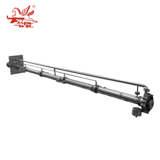
Lhy Sulphur Sump Pump: Cantilever Pump for High-Temperature Liquid Handling
| US$500.00-50,000.00 | 1 Piece (MOQ) |
Basic Info.
Model NO.
LHY pump
Driving Type
Motor
Impeller Number
Single-Stage Pump
Working Pressure
Low Pressure Pump
Influent Type of Impeller
Single Suction Pump
Position of Pump Shaft
Vertical Pump
Pump Casing Combined
Verticaljoint Surface Pump
Mounting Height
Suction Centrifugal
Impeller
Closed
Usage
Pump, Pumps, Condensate Pump, Slurry Pump, Circulating Pump
Capacity
0.2~400m3/H
Head
~150m
Pressure
~1.6MPa
Temperature
500 Degrees
Standard
ISO2858/GB5656
Rotation Speed
2900, 1450
Transport Package
Plywood Box
Trademark
Feiyue
Origin
Jiangsu, China
Production Capacity
5000
Product Description
Product Description Lhy Vertical Sump Pump Submersible Pump For Liquid Sulphur PumpConform to design standard of 1S02858/GB5656 Flow range: 0.2~400m3/h
Lift range: ~150m
Design pressure: 1.6MPa Application temperature: ~500ºC
Application field: This series of pump is mainly used in sulphuric acid, pyrite acid sulfur recovery, coal chemical industry, petroleum cracking of sulfur recovery and other material need heat preservation conditions. Summary
Sulfur pump with small flow capacity, high delivery lift, is developed on the strength of previous sulfur acid pump, coll aborated with institutes, colleges, it is characteristic of high delivery lift andsmall flow capacity, impossibly achieved by centrifugal pump, while unstable performance existing during operation of volute pump. There for, adopt latest hy draulic design, integrating unique advantages of centrifugal pump and volute pump. It has filled in domestic gap, reac hed international advanced level, able to substitute for impo ted ones, economizing relevant investment, widely used in acid making procedure to convey liquefied sulfur under 130-158ºC, with improvement, it also can be used under ot her hi - temperature and insulation working conditions.
Parameter range
Capacity:Q:0.2-400m3/h
Head:H:2-150m
Temperature:T:500ºC
Pressure:P:1.6MPa
Under water depth:L:0.5-5m
Meaning of model code
2-Capacity
120-Head
1-Under water depth
LHY-Feiyue Sulfur pump code
Chart
| 1 | Before the pump cover | 2 | Impeller nut | 3 | Pump body | 4 | Impeller | 5 | Elbow | 6 | Under the collar |
| 7 | Bushing | 8 | Liquid pipe | 9 | Intermediate to take over | 10 | Pump shaft | 11 | Packing collar | 12 | Stuffing box |
| 13 | Packing gland | 14 | Bearing box | 15 | Bearing cover | 16 | Bearing | 17 | Bearing | 18 | Lock nut |
| 19 | Bearing cover | 20 | Electric frame | 21 | On taking over | 22 | Bushing gland | 23 | On the liner | 24 | Guide bearing |
| 1 | Screen | 2 | Under the collar component 1 | 3 | Entrance section | 4 | Impeller 4 | 5 | Lock nut,bolt(4) | 6 | Guide vane 4 |
| 7 | Pump body | 8 | Balancing drum | 9 | Under the collar component 2 | 10 | Take over(steam pipe) | 11 | Take 2 in the middle(steam pipe) | 12 | Intermediate shat sleeve component(2) |
| 13 | Middle bearing | 14 | Shaft | 15 | Among over 1(steam pipe) | 16 | Coupling collar | 17 | Coupling shaft snap ring | 18 | Intermediate to take over |
| 19 | On the shaft | 20 | Steam over | 21 | On taking over | 22 | Floor | 23 | Bearing box | 24 | Packing gland |
| 25 | On the shaft sleeve 1 | 26 | Collar 2 | 27 | Bearing | 28 | Bearing gland | 29 | Dowel pin coupling | 30 | Electric trame |
| 31 | Motor |
Company Profile
FAQ
>> Peanut Picking Machine for Sale
>> byloo Outdoor China wholesale high quality 2 pieces portable travel casting rod with baitcasting reel combo fishing rod set
>> Internal Built-in Rohs 5G 4G LTE 3G 2.4G WIFI 2G GSM Lora IPEX U.FL Flexible FPC PCB Antenna Manufacturer for GSM Module
>> Ningbo Sanzhaoda Motorcycle Scooter brass/zinc Tubeless Tire Valves pvr32 Motocicleta valvula PVR30 PVR32
>> Jb-720A/800A/1020A/1050A Fully Auto Screen Printing Machine-Auto Flat Screen Press
>> OEM New S19 Control Board for L7 E9 PRO Ka3 Main Board Mother Boards
>> Offroad Heavy Duty Spare Tire Garbage Bag for Overlanding Accessories SUV Trunk Organizer Cargo Tool Storage Bag
>> Plastic Crushing Machine Shredder Blade Box
>> Drop-on Application Glass Beads Used on Road Marking Reflective BS6088 Standard
>> High Tech IGBT Infineon IGBT Transistor
>> CNC Machine Tool Lathe Roll Rebar Machine for Metal Cutting
>> Reliable Performance Waste Tire Cutting Machine Tire Wire Extractor
>> Sanitary Ware Ceramic Balcony Ceramic Countertop Wash Bathroom Basin
>> Bean Grain Pulses Sesame Seed Pouch / Packaging Bag Food Plastic Vacuum Bag Snack Heat Seal Gravure Printing CPP Recyclable 02
>> 12 Strand UHMWPE/Hmpe Marine Towing Rope for Mooring Offshore Winch Rope
>> OEM Cheap Plastic Box Packaging Mint Flavor 50m Dental Floss
>> PP PE Film Recycling Machine
>> Fashion Unisex Women Men Sport Custom Winter Knitted Hats with Logo Beanie Hats Warm Ski Caps
>> Disposable blue kiddies theme birthday party disposable napkin cutlery paper set plate tray cup
>> HC-R032 Veterinary Doppler Blood Pressure /pet doppler ambulatory blood pressure equipment for animals
>> new design turn board Ballet Spin dance Turning Board
>> Zoomlion Actros 4141 52m Second Hand Diesel Truck Mounted Concrete Pump Piston Rod Concrete Pump Truck Piston Rod Concrete Pump Truck
>> Medical CE approved portable fractional co2 laser
>> hydrogen water tumbler mini hydrogen water generator
>> Wholesale high quality T-shirts for Men v-neck custom pattern logo premium designs comfortable fitting OEM ODM
>> Personalized Custom Die Casting High Quality Fashion Enamel Lapel Pin
>> Turnkey Project Feed Factory for Livestock Poultry Feed Processing Line
>> REVO Timing Kit Chains Auto Accessories Engine Car Parts M160 E6AL B05 0.6L TK1027-11
>> Construction Small Excavator Agricultural Use Crawler Hydraulic Mini Backhoe Loader Bucket
>> 20kHz 2000W Ultrasonic Plastics Welding Machine Generator System Ultrasonic Generator System