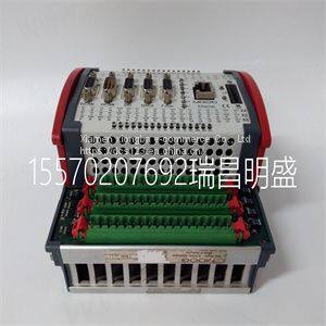
Module spare parts D136-001-001
Product Details
Product Details
Product Description
Product DescriptionFocus on DCS, PLC, robot control system and large servo system.
Main products: various modules / cards, controllers, touch screens, servo drivers.
Advantages: supply of imported original products, professional production parts,
Fast delivery, accurate delivery time,
The main brands include ABB Bailey, Ge / fuanc, Foxboro, Invensys Triconex, Bently, A-B Rockwell, Emerson, ovation, Motorola, xyvom, Honeywell, Rexroth, KUKA, Ni, Deif, Yokogawa, Woodward, Ryan, Schneider, Yaskawa, Moog, prosoft and other brands
| D136-001-001 |
>> Sqmg 5.5 Cbm Self-Loading Diesel Concrete Mixer for Manufacturing and Construction
>> 4 handles stimulateur musculaire slimming machine with RF EMS muscle stimulator electromagnetic
>> ISP Network Cabinet Installation Cloud Core Router Mikrotik Ccr2004-16g-2s+ 16X Router
>> Hot sale & high quality Tracker Front bumper stopper L For Chevrolet 26227735
>> 4K 60Hz 1.2m 2m 3m Male to Male Mini HDMI to HDMI Cable
>> Good Quality Accessories Light Luxury All Brass Ornaments Horse Antique Indoor Animal Sculpture Modern Home Decor
>> 1400-2200mm Fingerless Single Ply Single Facer Corrugated Machine for Corrugated Paper Making
>> PPD512 A10-454000 ABB module supply
>> Small Carrot Pumpkin Chopping Machine Multifunctional Snack Processing Equipment
>> Camouflage Virgin Rubber Bumper Barbell Plate
>> Ybjg-003/Cast Iron Manhole Cover/Manhole Cover/Casting/Grating/Building Material/Ductile Iron Manhole Cover
>> Vmc855 Vertical Machining Center Made in China
>> Electric Power Drill 800W 900W Magnetic Drill Machine Jc13A Jc16A Jc28A Jc32A
>> Low Price Made in China Mini Crawler Digger Earth-Moving Machinery Mini Excavator Recruit Agent 2.6 Ton Micro Digger Bagger 2600kg Excavators
>> China Manufacture 1000-610 Long Span Roofing Sheet Roll Forming Machine Customized K Span Roll Forming Machine
>> Taijia Portable Concrete Rebar detector Scanner for sale Integrated rebar detector
>> 11432.6 Kg 1years Agricultural Machinery Self Propelled Tractor Boom Sprayer for Sale
>> 70.87"Modern Minimalist "T" Shape Dining Table for 6wishglossy Sintered Stone Tabletop, Stainless Steel Base
>> Black Electrophoretic Paint Drywall Screw
>> Responsive Soccer Ball for Youth Soccer Practice
>> Film Hot Tack Tester
>> Automatic Animal Feed Grass Cutting Machine Grass Chopper Machine
>> Sephcare edible food color powder E153 vegetable carbon black food colorants
>> Customized FRP Fiber Reinforced Fiberglass Pipe Making Machine
>> Sealed Hammer Crusher-Coal Sample Preparation Equipment
>> Ss SUS 201 304 304L 316 316L 309S 310S 321 430 904L Hot Rolled/Cold Rolled 2b/Ba/Hairline/Mirror/No. 1 Surface 304 Stainless Steel Coil
>> Plastic Combination Flower Pot Urn Shape (KD2922-KD2925)
>> Manufacturer Wholesale Custom New Design of High Quality Football Religious Club Military Volunteer Religion School Metal Epaulets Cap Police Logo Coin Badges
>> Manufacturers Fitness Mini Indoor Kids Trampoline 16ft Bounce Trampoline Exterieur Big Round Trampolin With no Enclosures
>> New OEM Brand High Quality Sheet Metal Cutting Machine Steel Sheet Shearing Machine Suppliers