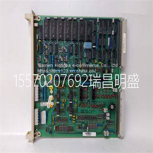
Module spare parts DSDP150 57160001-GF
Product Details
Product Details
Product Description
Product DescriptionFocus on DCS, PLC, robot control system and large servo system.
Main products: various modules / cards, controllers, touch screens, servo drivers.
Advantages: supply of imported original products, professional production parts,
Fast delivery, accurate delivery time,
The main brands include ABB Bailey, Ge / fuanc, Foxboro, Invensys Triconex, Bently, A-B Rockwell, Emerson, ovation, Motorola, xyvom, Honeywell, Rexroth, KUKA, Ni, Deif, Yokogawa, Woodward, Ryan, Schneider, Yaskawa, Moog, prosoft and other brands
| DSDP150 57160001-GF |
>> Industrial Scale Decanter Centrifuge machine
>> 20L (Single station & Single head & Two layer) Blow Moulding / Molding Machine
>> CNC Wood Craft Machine for Wood Engraving Cutting
>> EG25-G Mini Pcie EG25 EC25 with sim card slot 4G LTE CAT4 Module
>> 5W 6W 7W 8W 10W 12W 20W 3CCT IP65 Hotel Project Living Room Kitchen Indoor LED Downlight Spotlight Lighting
>> Hand Type Multifunctional Double Heads Double Motors Thread Trimming Machine for Shoes Clothes
>> Car Front grille Auto Parts Intake grille for kia picanto 2012 86350-1Y500
>> Electric Multifunctional Vacuum Pet Grooming Kit Tools Dog Hair Cleaning Nails Cat Grooming vacuum Cleaner
>> Multi-function constant temperature milk mixer, two in one milk warm sterilizer, intelligent baby milk powder heat preservation
>> Quick Install Cheap Price Prefabricated Workshop
>> High-Performance 1000W 1200W Two Wheel Electric Scooter for City Commuting
>> Jyl08, CE, ENEC, CB, RoHS, AC100-240V, IP66, 60W, 100W, 150W, 200W Die Casting Aluminum SMD LED Street Lamp
>> Gold Plated 3.5 3-Pole Jack Trs Connector Metal Head Plug Aux Stereo Cable Audio Auxiliary Extension Headset Cable
>> Hot Sale All Over Full Printed Design Heat Transfer Printing Gift Customized Golf Umbrella (GOL-0030FA(C))
>> Natural Custom White High-Temperature Resistant Solid Engineering Plastic Product UHMWPE Rod
>> New Style Black Color Salon Barber Equipment Wash Shampoo Chair
>> Bowling Lanes Kids Adult Fun Indoor Bowling Facilities High-Quality Bowling Equipment
>> Hotel foldable cloakroom concealed ironing board cheap wall mounted lroning board cabinet lroning board hanger
>> Mini Disc Plough Discs Plough Mini Tractor Plough Walking Tractor Farm Machinery Argricultral Machinery
>> High Definition PE Transparent Base Paint for Wood and Wooden Furniture
>> Multifunctional 4 Outlets Power Strip with 2 USB and Instruction Light
>> Lt Nij Iiia PE Aramid Ud Fabric 215GSM Aramid Woven Fabric Ballistic Fabrics
>> High Pressure Air Hose
>> Wholesale 4oz 210ml 220ml Glass Frost Candle Cup for Candle Making with Sealing Bamboo Lid for Wishing Birthday Party Wedding
>> Sign A4-1325-L8-E Atc CNC Router Cutting Machine with Automatic 8 Tools Engraving
>> High Precision Swiss CNC Lathe Machine with 3 Axis Travel CNC
>> Unisex Soft Solid Color Black Winter Custom Logo Acrylic Knitted Beanie Hat
>> T3 Series Water Flow Meter Commercial Residential Ultrasonic Water Meter Dual Channel Industrial Ultrasonic Water Meter
>> Hg127 Cheaper/ERW Tube Mill/ High Frequency Welding ERW Steel Tube Mill /Pipe Mill Machine
>> Factory Supply Pumpkin Seed Harvester Extractor