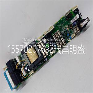
Module spare parts DSMB-01C 64691929
Product Details
Product Details
Product Description
Product DescriptionFocus on DCS, PLC, robot control system and large servo system.
Main products: various modules / cards, controllers, touch screens, servo drivers.
Advantages: supply of imported original products, professional production parts,
Fast delivery, accurate delivery time,
The main brands include ABB Bailey, Ge / fuanc, Foxboro, Invensys Triconex, Bently, A-B Rockwell, Emerson, ovation, Motorola, xyvom, Honeywell, Rexroth, KUKA, Ni, Deif, Yokogawa, Woodward, Ryan, Schneider, Yaskawa, Moog, prosoft and other brands
| DSMB-01C 64691929 |
>> Yuever Medical Veterinary Operating Table Surgery Tables Veterinary Veterinary Surgical Table for Animals
>> DIN7991 Grade 10.9 Flat Socket Head Cap Screw
>> 60ml 100ml 200ml Fiber Optic 250ml Alcohol Bottle
>> Luxury top-end wooden Jewelry storage box
>> Sc APC Sm Simplex Fiber Optic Patch Cord
>> Ahyw Ywt 300t Electro Hydraulic Press Brake Bending Machine
>> Reliable Die Casting Parts for Precision Aluminum Alloy Fabrication Services
>> 3-tier retangular Storage rack Freestanding Storage Organizer Shelf 3tiers corner shower caddy shower shampoo rack
>> China′s Top Supplier of Layers Chicken Battery Cages
>> Injection Moulding Machine Big Size Plastic Injection Molding Machine
>> China Manufacturer Private Label OEM Fresh Vegetable Canned Cream Sweet Corn
>> 4" Chinese Factory Line Shape RGB Safety Zone Red Stop Forklift Warning Lights
>> New Design Rubber Hand Grip, Gym Palm Protector
>> 6201 6202 6203 6205 6206 Auto bearing/vehicle bearing/wheeler bearing/motorcycle spare parts/auto parts/Conveyor bearing /ceiling fan bearings/radial bearing
>> Hydraulic Radial Drilling Machine (RD series)
>> Cts Customized 48V60V72V 100ah 150ah 200ah LFP Battery with IP67 Waterproof Level Housing
>> Single Beam Side Scan Food X-ray Inspection System for Bottle, Cans Product with FDA (FXR-C180)
>> Floating and Sinking Aquarium Fish Feed Mill Pellet Extruder for Fish Food
>> Factory Direct Black Anodizing Aluminum 6061 Charge Pile Shell Stamping Part for New Energy
>> Trendy Color Matching Red Gold Snake Pattern Leather Pointed Toe Stiletto Heel Ankle Boots Women Short Boots High Heels Booties
>> Vertical Z5045C conventional high precision drilling machine with CE
>> A312 Smls Stainless Steel Pipe (304H Tp304H 304 316 310 347 2205)
>> Toplift OEM Manufacturer Manual Hand Crank Cable Winch for Pulling Trailer Boat
>> Wholesale Women′s Body Shapewear Corset Top with 15 Steel Bones
>> Within 25-30 Days AC FUJI High Quality Export Wooden Case Elevator Sightseeing
>> Truck Repair Lift Car Jacks 30 40 50 80 100 180 200 Ton Pneumatic Air Hydraulic Jack
>> high temperature resist aluminum foil retort pouch bag cooking bag
>> High Efficiency Fine Crusher Pcx1212 for Sand Making Plant
>> High Efficiency Grain Sorghum Rice Millet Automatic Thresher Machine Factory Low Price
>> 300kg Capacity 12m Working Height Self-Propelled Electric Scissor Lift