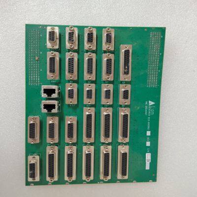
LAM 810-800082-043
Product Details
Product Details
Product Description
Product DescriptionBrand: LAM
Type:810-800082-043
Origin: the United States
Warranty: 365 days
Colour: new/used
Shipping method: Courier delivery
Module of PLC, DCS, ESD system card, the card is a vibration monitoring system, steam turbine control system module, the advantages of the gas generator spare parts brand: Allen Bradley, BentlyNevada, ABB, Emerson Ovation, Honeywell DCS, Rockwell ICS Triplex, FOXBORO, Schneider PLC, GE Fanuc, Motorola, HIMA, TRICONEX, Prosoft etc. Various kinds of imported industrial parts of our products are widely used in metallurgy, petroleum, glass, aluminum manufacturing, petrochemical industry, coal mine, papermaking, printing, textile printing and dyeing, mechanical, electronic manufacturing, automobile manufacturing, plastic machinery, electric power, water conservancy, water treatment/environmental protection, boiler heating, energy, power transmission and distribution and so on.
Relay Program Errors Relay #x Program Error—The specified relay was programmed for a function that is not also programmed to be used. Either the relay was mis-programmed or the function required is mis-programmed. For example, relay #1 is programmed for Remote Cascade Setpoint Enabled but Remote Cascade Setpoint was not programmed under the Cascade Program Block. Readout Program Errors Readout #x Program Err—The specified readout was programmed for a function that is not also programmed to be used. Either the readout was misprogrammed or the function required is mis-programmed. For example, readout #1 is programmed for Cascade Setpoint but Cascade Control was not programmed under the Cascade Program Block. Valve / Actuator Calibration and Test Before initial operation or after a turbine overhaul where any actuator or valve travel may have been affected, the below Valve Calibration procedure should be followed to insure that the 505E is calibrated to both valves. The 505E uses its actuator output currents to sense HP and LP valve positions. These valve positions are used by the 505E to calculate internal turbine ratios, and operating limits. Thus if the 505E is not correctly calibrated to each control valves actual travel, it will incorrectly calculate turbine operating limits. It is recommend that each valve be manually stroked after the 505E’s output has been calibrated to insure that the 505E’s screen and actual valve position match as closely as possible.
After a valid program has been entered the actuator and valve minimum and maximum positions can be adjusted and tested, if needed. Actuator and valve positions are determined by the drive current to the actuator. The maximum actuator current can not be adjusted lower than the minimum actuator current (see Table 4-1 below). The minimum actuator current can not be adjusted higher than the maximum actuator current. The driver current ranges are determined by the setting in the Program Mode under the Driver Configuration Block. When adjusting or testing actuator and valve travel, verify that sufficient valve over travel at the minimum stop is achieved (1-2%). This assures that each valve can fully close to completely shut off the steam flow to the turbine.
>> Mixed Flow Parboiled Paddy 35-500 Ton Day Rice Grain Dryer
>> Galvanized Poultry Farm Layer Chicken Cage Equipment
>> Easy Operation Machinery 100/200/300/600/1000/2400t Compression Press Vulcanizing Machine
>> Single Acting Hollow Plunger Hydraulic Cylinder Jack Tool Rch
>> Commercial Observation Passenger Lift Glass Sightseeing Elevator with Good Safety
>> Professional Factory Supply Green Belt Building Machine
>> DHL to Kenya Price for Wholesale Kenya Uganda Clothes From Yiwu Market to Kenya Shipping by Express Delivery
>> Sunpal Complete Solar Kit 5Kw 10Kw 15Kw On Grid Grid Tie Solar System For Home
>> Single Head Apparel Factory Price Multi Function Embroidery Machines Computerized
>> OEM Custom Precision Machining Steel Automotive Metal Parts CNC Milling Service
>> 20khz 2600W manual ultrasonic acrylic card slab case welding machine
>> Self-Loading Concrete Mixer Truck Self-Priming Driven Pump, 24V Self-Timing Centrifugal Pump, Hydraulic High-Pressure Car Engine Customizable 4.0m3 (2.6-4.5m3)
>> 12V DC Permanent Magnet Motor with Worm Reducer for Garage Door
>> Carbonless Customized Book Duplicate 50carbonless Sets 2parts with Perforated Lines and Consecutive Numbers
>> Rubber Deflashing Machine Rubber Separator
>> Largest Scale High Quality Forest Wood Drum Chipper Grinder
>> CNC Hydraulic Metal Stainless Steel Aluminum Shearing Guillotine Cutting Shearing Machine
>> Automatic AC Voltage Regulator SBW Three-Phase Auto High-Power Compensated Control Circuit AVR 220V SVC Factory Price Customizable OEM Ahkbdq
>> Lockable Power Inlet/Powercon Connector/Powercon True1 Connector
>> Farm Machinery Grain Flour Mill Rice Maize Milling Machine
>> Professional Low -E Clear Buliding Insulated Glass
>> State-of-The-Art Nano Laser Cutting Machine for FPC Windows
>> 2020 New Arrival Fodable Small Baby Trampoline with Customize M01A005
>> Factory Wholesale Nordic Ins Glass Dishes Western Food Plate Gold Rim Home Wedding Hotel Steak Pad Plate Glass Charger Plate
>> P10 Square Bluetooth Speaker Loudspeaker USB RGB Light Rechargeable Digital Display Alarm Clock Speaker
>> High Speed Vibrating Knife Precision Rubber Plastic Foam Gasket Pneumatic Knife Cutting Machine
>> Chinese Supplier Customize High Quality 220V Bluetooth Headset Welding Ultrasonic Plastic Welding Machine
>> Spc Rigid Vinyl Floor Tile PVC Plank Sheet Production Machine
>> Huasifei 10 Port Unmanaged Intelligent Poe Switch for Hotels to Form Cost-Effective Networks
>> G-View C6 Factory Wholesale LED Headlight 9005 HB3 9006 HB4 H11 H4 H7 LED Headlight China 6000K Light Bulbs C6 LED Headlight