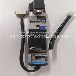
Module spare parts TNA1-TU01-SH
Product Details
Product Details
Product Description
Product DescriptionFocus on DCS, PLC, robot control system and large servo system.
Main products: various modules / cards, controllers, touch screens, servo drivers.
Advantages: supply of imported original products, professional production parts,
Fast delivery, accurate delivery time,
The main brands include ABB Bailey, Ge / fuanc, Foxboro, Invensys Triconex, Bently, A-B Rockwell, Emerson, ovation, Motorola, xyvom, Honeywell, Rexroth, KUKA, Ni, Deif, Yokogawa, Woodward, Ryan, Schneider, Yaskawa, Moog, prosoft and other brands
| TNA1-TU01-SH |
>> Grain Wheat Soyabean Barley Sorghum Corn Hammer Mill / Grinder for Maize Stalk/ Maize Grinding Mill
>> New Arrival Electric Tricycle Kit Electric Baby Tricycle Electric Tricycles Precio for Sale
>> Simple Modern 12V AC DC Hologram Display Screen 3D Hologram Fan 16" Spare Part Large Stand Fan
>> High Quality 5m3 2.16MPa Liquid CO2 Cryogenic Storage Tank in Stock for Sale
>> Aqualand 38feet 11.5m Fiberglass Luxury Rib Sport Leisure Dive Fishing Aluminium Rigid Inflatable Aluminum Speed Diving Rescue Patrol Yacht Motor Boat
>> Beautiful Christmas Printed Sherpa Blanket for Home
>> Manufacturer Commercial Use Home Use Qlick Click Spc Flooring 4/5/6mm with IXPE
>> Portable Chainsaw Mill Log Wood Cutting Chain Sawmill
>> Wholesale Quantity Exporter of Biscuit Beige Color Stylish A/B Grade Leather Gloves from India
>> 4FT Wood Log Debarker Machine Rotary Lathe for Peeling Tree Bark
>> Ornamental Floating Sinking Fish Food Extruder Line Aquatic Feed Make Machine
>> Lane 2-4t/H Extruder Fish Feed Machine Manual Feed Pellet Machine Animal Feed Making Machine
>> Best Price Telescope Nitrogen Filled Ipx7 Waterproof Binoculars 28X110 34X110 40X110 for Outdoor Activities
>> Hot Sale Indoor New Recessed Mounted 7W LED Spotlight
>> 2024 New Design Portable Fiber Laser Marking Machine Metal Stainless Steel Plastic Nameplate Engraving Gold and Silver Jewelry Engraving Machine
>> Semi Autoamtic Square Napkin Tissue Paper Making Machine Production Line
>> Modern Simple Coffee Table Small Dining Table Wholesale Prices Support Customization
>> Laizhou Auto Spare Parts Brake Rotor Pads Brake Disc with Ts16949
>> Custom CNC Machining Machined Auto Motorcycle Accessories Electric Transmission Car Spare Part Conversion Kit Dirt Bike Brush Cutter Embroidery Machine Parts
>> Rims Factory Whosale W11X24 Agricultural Tractor Steel Rims 11*24 Inch Wheels for 12.4-24 Tire Rim
>> Triple Salt Box Three Tier Bamboo Storage Box with Magnetic Swivel Lids
>> CW Volvo VHD auto ac blower fan motor Freightliner Century Class 85104207 BOA94350 BOAD8587 7337080401
>> reed leaves rope making machine
>> Circular Shape Electric Lifting Magnet for Steel Scrap of 700mm Diameter MW5-70L/1
>> Custom Design Printed Gym fitness yoga Sexy ladies singlets tank top gym one color pure cotton singlet for women girls
>> Zhongli 4 Axis Granite CNC Cutting Machine with Factory Price
>> Chicken Manure Compost Poultry Equipment Fertilizer Mixer Fertilizer Machine Poultry Livestock Machinery
>> High Quality Wholesale Custom Cheap sunice smart film building window glasses spd with
>> High Precision Horizontal Lathe with Slant Bed High-Speed and Efficient Horizontal Slant-Bed Lathe Ck-6180
>> C Axis 180 Angle 4 5 Axis CNC Milling Machine Kit for Foam EPS Wood