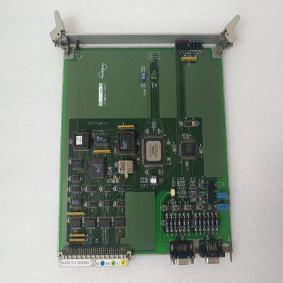
TEAM BL0308
Product Details
Product Details
Product Description
Product DescriptionBrand:TEAM
Type:BL0308
Origin: the United States
Warranty: 365 days
Colour: new/used
Shipping method: Courier delivery
Module of PLC, DCS, ESD system card, the card is a vibration monitoring system, steam turbine control system module, the advantages of the gas generator spare parts brand: Allen Bradley, BentlyNevada, ABB, Emerson Ovation, Honeywell DCS, Rockwell ICS Triplex, FOXBORO, Schneider PLC, GE Fanuc, Motorola, HIMA, TRICONEX, Prosoft etc. Various kinds of imported industrial parts of our products are widely used in metallurgy, petroleum, glass, aluminum manufacturing, petrochemical industry, coal mine, papermaking, printing, textile printing and dyeing, mechanical, electronic manufacturing, automobile manufacturing, plastic machinery, electric power, water conservancy, water treatment/environmental protection, boiler heating, energy, power transmission and distribution and so on.
APPENDIX A – DC POWER SUPPLY DESIGN A.1 DESIGN This section has additional considerations for DC power supplies. A.1.1 Single Power Supply Operation A single power supply can be used to provide main or motor power and control power for the DC power input. The voltage range of a single supply is 20 V to 90 V. NOTE The drive can be damaged if the supply voltage exceeds 90 V, even briefly. The DC level plus transients plus regenerative pump up MUST NEVER exceed 90 V. Wire the single supply +terminal to J1-3 (+Bus) and to J1-1 (+CTRL) and the power supply –terminal to J1-2 (Bus/Ctrl Gnd). This power supply is typically unregulated, but a regulated supply can also be used. The power supply outputs must be isolated from the power line. See Regulatory Information for more details on isolation requirements. Wire both the power supply negative terminal and the drive chassis to earth for safety. The maximum continuous and peak (3 sec) main power and current at 75 V bus for the S200 DC drives is shown in the table below. 3/9 ARMS S200 DC 6/18 ARMS S200 DC 250 watts 500 watts Main (continuous) 3.33 ADC at 75 V 6.67 ADC at 75 V 750 watt 1,500 watt Main Peak (3 sec) 10 ADC at 75 V 20 ADC at 75 V The next figures provide representative connection diagrams and some detailed recommendations.
An appropriately-sized output capacitor in the main power supply is the key to economically delivering high peak power. In most applications, the capacitor supplies much of the peak power needed to accelerate the motor and inertia (under 20 ms). It also lowers the cost of the supply by reducing its silicon current. In addition, it also absorbs regenerated energy with a limited pump up of voltage and stabilizes the bus voltage for better dynamics. NOTE While the maximum peak-to-continuous power capability is 3:1, most applications have much higher ratios. The requirement that the main supply have a high peak-to-continuous power ratio is very important in selecting or designing the power supply
Main Supply Output Capacitance (J1-3 to J1-2) NOTE The location of the main output capacitor is not critical. Up to 10 ft from the drive is an acceptable length, as long as the wire is sized so resistive drops at peak current are low. Voltage clipping of the inverter can cause the peak bus current to equal the motor current. A good rule is to size the bus wiring for 18 ARMS x rt(2) = 25.4 ARMS peak per drive. Use at least 16 AWG. The inductance of the bus and ground wiring is not critical because the internal drive bus capacitance can handle all the PWM current in most cases.
>> DC AC Voltage Diode Freguence Multimeter Volt Tester LCD Digital Multimeter
>> Mobile Hydraulic Crawler Mine Hard Rock Separated DTH Small Bore Hole Drilling Machine
>> Ergonomic Middle Back Adjustable Tilting Staff Task Home Office Swivel Chair
>> 21 Inch Unisex Educational Throwing Target Game Set Includes Axes Darts Stars and Archery Dartboard Shooting Toys for Kids
>> 50 conector OM RF 4.3-10 Mini Din conector de enchufe para cables 1 / 2 blandos in Brazil
>> Made In China Garden Waterproof Exclusive Motor Retractable Pergola Roof Awning
>> Vertical Axis Fine Crusher (PCL750-3~1250-3)
>> New Original Nvidia Rtx A6000 Graphics Card 48GB Gddr6 Gaming Graphics Cards Video Card Gaming Rtx A6000 A5000 A4000 A2000 Graphic Cards
>> 2 Ply PVC Silver Anti Light Projection Film
>> Decorative Crystal Mirror Glass Mosaic Tile for Bathroom /Hotel/Casino/Hotel Project Wall Decorations
>> Chloris High Quality 6 Pieces Piano Tuning Tool Kits for Sale
>> Carbon Seal
>> Lab Scale Wool and Cotton Fancy Ring Spinning Machine
>> 7g 10g 13G Computerized Knitted Gloves Making Machine, Glove Knitting Machine
>> New Design Auto 200-5000kg/H 380V Ring Die Biomass Pellet Machine Briquette Machine Granulator Pelletizer Pellet Press Wood Pellet Machine Line
>> Z/1100 Two Platen Injection Blow Molding Production Line
>> Steel Wheel Rim Coiler Machine with Automatic Feeding
>> couple watches 9210 sweet quartz watch for men and women luxury lovers blank private label watch wrist hour
>> Custom Logo Printing Canvas Tropical Caribbean Virgin Islands St Martin St. Lucia Souvenir Beach Tote Bag
>> High Precision Single and Double Sided Round Knives for Cutting Tape, Film in Industry
>> High Efficiency Device Paper Normal Size Hard Paper Shredder Machine
>> Large Trinity Corten Steel Outdoor Sculpture
>> High Precision CNC Lathe Slant Bed Small CNC Lathe Turning Machine
>> China Wholesale Cheap High Quality Disposable Bamboo Fruit Skewers
>> Sturdy Slant Bed CNC Lathe for Precise Seal Fabrication (BL-S36S)
>> CE Certification Boats 25FT 7.9m Aluminum Deep-V Bottom Marine Grade Fishing Boats
>> Carbide Bushings Supplier Tungsten Carbide Bushing for Oil Gas Industry
>> Wholesale Aijiren 20ml ND20 Crimp Headspace Gc Clear Glass Vial
>> 18′′/20′′aluminium Alloy Kids Bicycle, Folding Features, Front and Rear Disc Brakes.
>> Handheld Portable Small USB Mini Night Color Ultra Quiet Office Desktop Fan