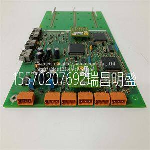
Module spare parts UFC721BE101 3BHE021889R0101
Product Details
Product Details
Product Description
Product DescriptionFocus on DCS, PLC, robot control system and large servo system.
Main products: various modules / cards, controllers, touch screens, servo drivers.
Advantages: supply of imported original products, professional production parts,
Fast delivery, accurate delivery time,
The main brands include ABB Bailey, Ge / fuanc, Foxboro, Invensys Triconex, Bently, A-B Rockwell, Emerson, ovation, Motorola, xyvom, Honeywell, Rexroth, KUKA, Ni, Deif, Yokogawa, Woodward, Ryan, Schneider, Yaskawa, Moog, prosoft and other brands
| UFC721BE101 3BHE021889R0101 |
To prevent the subharmonic oscillations, a compensation ramp is added to the control signal, as shown in Figure 21. With the compensation ramp, ΔVsamp1 and the convergence criteria are expressed by, (11) (12) The compensation ramp has been added internally in the LM3481. The slope of this compensation ramp has been selected to satisfy most applications, and it's value depends on the switching frequency. This slope can be calculated using the formula: MC = VSL x fS (13) In Equation 13, VSL is the amplitude of the internal compensation ramp and fS is the controller's switching frequency. Limits for VSL have been specified in the Electrical Characteristics section. To provide the user additional flexibility, a patented scheme has been implemented inside the IC to increase the slope of the compensation ramp externally, if the need arises. Adding a single external resistor, RSL(as shown in Figure 23) increases the amplitude of the compensation ramp as shown in Figure 22. Figure 22. Additional Slope Compensation Added Using External Resistor RSL Where, ΔVSL = K x RSL (14) K = 40 µA typically and changes slightly as the switching frequency changes. Figure 24 shows the effect the current K has on ΔVSLand different values of RSL as the switching frequency changes. A more general equation for the slope compensation ramp, MC, is shown below to include ΔVSL caused by the resistor RSL. MC = (VSL + ΔVSL) x fS (15) RFA = fS 22 x 103 - 5.74 LM3481 DR ISEN RSEN VIN L1 D1 Q1 COUT VOUT RSL + CSEN 15 LM3481, LM3481-Q1 SNVS346F –NOVEMBER 2007–REVISED NOVEMBER 2014 Product Folder Links: LM3481 LM3481-Q1 Copyright © 2007–2014, Texas Instruments Incorporated Submit Documentation Feedback Feature Description (continued) It is good design practice to only add as much slope compensation as needed to avoid subharmonic oscillation. Additional slope compensation minimizes the influence of the sensed current in the control loop. With very large slope compensation the control loop characteristics are similar to a voltage mode regulator which compares the error voltage to a saw tooth waveform rather than the inductor current. Figure 23. Increasing the Slope of the Compensation Ramp Figure 24. ΔVSL vs RSL 7.3.4 Frequency Adjust, Synchronization, and Shutdown The switching frequency of the LM3481 can be adjusted between 100 kHz and 1 MHz using a single external resistor. This resistor must be connected between the FA/SYNC/SD pin and ground, as shown in Figure 25. Refer to the Typical Characteristics to determine the value of the resistor required for a desired switching frequency. Equation 16 can also be used to estimate the frequency adjust resistor. Where fS is in kHz and RFA
>> High Quality Agricultural Grass Shredder for Cattle and Sheep Corn Wheat Straw Shredder
>> Single/Double Plough for 20HP Two-Wheeled Walking Tractors
>> Vico Ezcalipre 3D Measuring System Auto Body Frame Measuring System Cutting-Edge Vehicle Body Measure
>> Modern Veranda Large Bi Folding Patio Burglar Proof Double Glass Accordion Design Partition Aluminium Folding Door Residential
>> Hydroneumatic Tank for Fire Sprinkler System′ S Water Supply
>> Premium Quality China Factory Judo Tatami Floor Mats, Taekwondo Floor Mat, Judo Mat, High Density Foam MMA Judo Tatami Mat, Floorings
>> Ruipuhua ZP-500SG Energy Bar Granola Cereal Bar Automatic Flow Wrapping Packing Machine For Chocolate Muesli Bar
>> Multipurpose CE Approved 2000-8000kg/H Sunflower Husk Waste Corn Stalk Wood Pellet Plant Wood Fuel Pellet Press Machine
>> Manufacturer Oscillating Knife Foam Rubber Cutting Machine with Good Quality
>> R&D factory design NFRC hurricane resistant sliding window for commercial cafe restaurant project double glazed impact windows
>> Hck 150 Ton Haichen Disposable Hookah Injection Plastic Molding Machine Hookah Hose Making Machine
>> Eco-Friendly Dental Floss Picks for Oral Hygiene
>> Walki Type Full Electric Pallet Trolley
>> High Quality Wire Braid En853 1sn Hydraulic Rubber Hose
>> Chinese Supplier Professional Factory 12000Btu 18000Btu Aircon Inverter
>> Baldan Disc Plough Fish 3 Disc Farm Implements Agricultural Machinery
>> CNC Prototyping Company Providing Quality Precision Machined Components
>> Custom Creative Design Gift Box High Fashion Folding Open Lid Optional Interior Shape OEM Eco-Friendly Cardboard Jewelry Gift Boxes Packaging, Shipping Boxes
>> 14inch and 15.6 Inch Best Price Custom Ultra-Thin Laptop Computer Students and Business Laptop
>> 16mm Mushroom Head Green Switch IP65 Normally Open Momentary Button
>> Mr-U2 Polishing Drill Bit Avoid Error Caused of Drilling in Precision Lathe Machine Machinery Plant
>> Module spare parts 216GD61a HESG324436R3-A HESG324428
>> Potato Harvesting Machine Tractor Farm Machinery Harvest Mini Machine
>> pure material plastic rod POM rod,10~200mm Plastic Polyoxymethylene POM Rods
>> Best Quality Commercial Furniture 2/3/4 Person Hospital Infusion Chair Stainless Steel Public Waiting Chair (UL-22MD99)
>> Advanced Industrial Colloidal Mill for Versatile Processing Needs
>> Hot Sale Architectural Stained Glass Custom Home Decor Glass Wall Art Glass Sheets
>> Apollo Kids Electric Bike 250W Electric Balance Bike
>> Best Value Hand Pallet Truck Scale Cylinder Weighing Scale for Hand Pallet Scale Truck Forklift for Sale
>> Direct Violet 1 Violet N 100% Cotton Textile Paper Direct Dyes