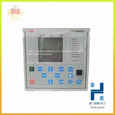
REF615 REF615C ABB module of feeder protection and measurement and control device
Product Details
Product Details
Product Description
Product DescriptionREF615 REF615C ABB module of feeder protection and measurement and control device
REF615 REF615C ABB module of feeder protection and measurement and control device
Our Email: 2235954483@qq.com
contact number:13313705507
contacts:HE
Installing the TRIO Fieldbus Interface CI862
The CI862 is powered from the processor unit via the CEX-Bus and requires no
additional external power source. No field device is powered from the CI862.
Use the following procedure to install the CI862:
1. Mount the unit onto the DIN-rail.
2. Connect the field bus cable to the LAN connector (right most connector). See
the CI862 Installation book for TRIO field bus guidelines, cable types and
length.
The Hand-Held Monitor, if used, is connected to the HHM connector.
Unit to Baseplate Alpha Code Lock
The CI862 unit and baseplate have the locking device removed because of the
placement of the electronics inside the unit. The electronics will not allow the CI862
unit to be installed in any baseplate with a locking device. However, other units
could be inserted into the CI862 baseplate.
Bus Termination
The appropriate terminating resistor must be attached to both the beginning and end
of the bus. The characteristic impedance for each type of cable is listed in Table 150.
If the CI862 is at either end of the bus, the characteristic resistance is set by a switch
on the Field Bus Interface Module, Table 16. If a TRIO module is at the beginning
or end of the bus, the bus can be terminated with a resistor or a terminating
resistance plug, 6202FP00150 for 150 W or 6202FP00075 for 75 W. BSM stubs
should not be terminated.
The CI862 baseplate has no locking device. Insert only the CI862 unit into this
baseplate. Insertion of other unit types may cause damage to the equipment.
Table 16. Field Bus Termination Switch Settings of the CI862
>> Factory Supply Agriculture Machinery Tractor Mounted Scraper Land Grader Pto Satellite Land Leveler
>> High-Performance Hydraulic Press Brake Molds for Heavy-Duty Bending
>> Medical Consumable Suit for Endoscope Channel Disposable Cleaning Brush with CE
>> Customise universal desktop bamboo wooden multiple mobile phone bracket holders stand support watch charging house
>> IC660ELD100A IC660ELB921M IC660ELB912G | GE FANUC MODULE PLC DCS In Stock
>> Oturncnc Metal Turning Machine Machine Ty106 Slant Bed CNC Turning Lathe Optional 3 Axis Type Turning Lathe
>> High Speed DTH Rock Drilling Rig Effective Working
>> High Quality Continuous Working Disc Separator Centrifuge Machine for Small Lime
>> 3D Brick Design Waterproof XPE Wall Foam Sticker
>> TUV Standard 8 Person Commercial Customized Stainless Steel Small Lift Elevator Cabin
>> Touch Screen Digital Benchtop Universal Metal Hardness Tester with Brinell Rockwell and Vickers Scales Analog Display
>> Automated N95 Face Mask Manufacturing Equipment for Kids
>> TOSHIBA 2N3A3620-B Controller brand new
>> Agriculture Planting Machine Seeyes 430 High-Speed Rice Transplanter 2zg-4qr
>> China Grain Processing Machinery Flour Miller/Self-Priming Wheat Flour Milling Grain Crusher/Best Price Hammer Mill Crusher
>> Digital high precision densimeter
>> Fiber Laser Welding Machine for Sealing Welding of Battery Shell and Cover 3000W
>> Building Material Machine CZ Section Construction Purlin Roll Forming Machine
>> Electric Heating-Extruded Welding Machine PVC-U Profile Structure Machinery Double Head Seamless Welding Machine
>> 50X~500X Magnification Infinity Optical Lab Instrument Mit300 LED Reflecting Metallurgical Microscope
>> Shock Absorber of Suspension System for Renault Clio II - R/ Thalia, Symbol - R 343289 F 333707
>> Portable Fractional Co2 Laser Skin Resurfacing Vaginal Tightening Machine With CE ISO ROHS
>> Wardrobe Layered Partition Cabinet Tube Dormitory Storage Telescopic Nail-Free Storage Kitchen Bathroom Rack
>> VIP Luxury City Bus Seat
>> HDPE/LDPE Filming Blowing Plastic Machine
>> Clean-Link Air Conditioner Filters Seamless Pocket Pre-Filter Filter Suppliers Filtre Ahu Filter
>> Customized Pig Feed Pellet Press Die Ring Die
>> Customized CNC Machined Stainless Steel Engine Bushings for Auto Parts
>> High Performance Foif Tc-032 4m 4 Section Survey Telescopic Leveling Staff
>> interior accessories for landcruiser fj200 lc200 interior kit 2012-2016