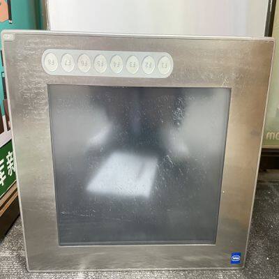
STAHL ET-436-AT-R2-HB-TX-100GB-V
Product Details
Product Details
Product Description
Product DescriptionBrand:STAHL
Type:ET-436-AT-R2-HB-TX-100GB-V
Origin: the United States
Warranty: 365 days
Colour: new/used
Shipping method: Courier delivery
Module of PLC, DCS, ESD system card, the card is a vibration monitoring system, steam turbine control system module, the advantages of the gas generator spare parts brand: Allen Bradley, BentlyNevada, ABB, Emerson Ovation, Honeywell DCS, Rockwell ICS Triplex, FOXBORO, Schneider PLC, GE Fanuc, Motorola, HIMA, TRICONEX, Prosoft etc. Various kinds of imported industrial parts
Our main products are widely used in metallurgy, petroleum, glass, aluminum manufacturing, petrochemical industry, coal mine, papermaking, printing, textile printing and dyeing, mechanical, electronic manufacturing, automobile manufacturing, plastic machinery, electric power, water conservancy, water treatment/environmental protection, boiler heating, energy, power transmission and distribution and so on.
In this operating mode the turbine’s HP and LP valve actions are fully decoupled. The HP valve can be positioned by the 505E’s Speed, Cascade, or Auxiliary PIDs. The LP valve can only be positioned by the 505E’s Extr/Adm PID. The decoupled configuration allows control of a turbine’s inlet pressure without interaction from exhaust flow changes. With this mode of operation, turbine exhaust pressure is controlled by only moving the LP valve. The turbine’s HP and LP valve actions are also decoupled to control turbine exhaust pressure/flow without interaction from turbine inlet pressure or flow changes. Turbine inlet pressure is controlled by only moving the HP valve, thus no change in exhaust pressure/flow is created. For a change in either process the respective valves are repositioned for a net effect of no pressure or flow change on the other process. With this mode of operation, turbine inlet pressure can be controlled through either the 505E’s Auxiliary or Cascade PIDs and turbine exhaust pressure is controlled through the Ext/Adm PID. Although turbine load is not controlled with this configuration, it is recommended to use the Auxiliary PID as a load limiter for unit protection. Block Diagram Description The block diagrams displayed below provide a detailed view of each Ratio/Limiter configuration and the relationship between the ratio/limiter’s input and output signals. The ‘S’ input signal originates from the Speed/auxiliary LSS buss and represents Speed, Load, Aux PID, or Casc PID demand. The ‘P’ input signal originates from the Ext/Adm PID or the E/A demand setpoint, depending on selected modes, and represents Ext/Adm flow demand. The ‘DC’ input signal is a discrete signal that originates from the control’s decoupling map logic and goes to a true state when ratio/limiter decoupling is selected. The ‘S’ and ‘P’ signals must pass through map limiters, depending on the priority selected, before they are used in the ratioing equations. Only one parameter (S or P) at a time can be limited, thus if speed priority is enabled, only the P signal is limited. If Ext/ Adm priority is selected, only the S signal is limited. These limiters allow the valves to be correctly positioned on each turbine operating limit. To simplify the limiter logic, the Min (HSS bus) and Max (LSS bus) limiters are displayed as one limiter bus. Each possible turbine operating limit is labeled and displayed graphically.
All Limiters are based on the entered steam map values and actual HP & LP valve positions (as derived from the control’s actuator driver signals). Once the ‘S’ and ‘P’ signals pass through their respective limiters, they are referred to as S’ (S-prime) and P’ (P-prime). When the turbine is not operating on a limit, the S’ value equals the S input signal and the P’ value equals the P input signal. If programmed for decoupled operation, digital ramps are used to transfer between Ratio/ Limiters. During normal enabling and disabling of the decoupled ratio/limiter mode, these ramps take 50 seconds to completely ramp from one ratio/limiter to the next. with generator applications, this transfer is made within 40 milliseconds when switching to frequency control (gen or tie breaker opens).
>> W11S-12X4000 Hydraulic upper roller universal plate bending rolling machine
>> Admixture Concrete Aluminium Powder Paste for Lightweight Concrete
>> TRICONEX AI2351 SIS safety system industrial control spare parts module
>> Medical Disposable Equipment Intravenous Infusion Set
>> Enclosed Whiteboard Magnet Planner Chalkboard Calendar for Fridge
>> Cr or Galvanized Fha Strap 16ga
>> Compact Electric Bench Drill Press
>> polyester cotton fiber opening pillow filling machine wool opener cotton waste fiber opener recycling machine
>> Advanced Design Bottle Filling Capping Machine for Liquid Makeup Foundation
>> motorcycle / motorbike / scooter tyre nozzle repair accessory VAMD161 TR161 air tire valve
>> Variable Speed Universal Lathe Turning Machine
>> Stainless steel expanded metal mesh for barbecue grill
>> 133mm Scroll Saw Blade,Power Tools
>> Fruit and Farm Individual Chain Tensioning Fruit Bin Carrier Trailer
>> AIS Modern Style Design Customized Home Furniture Handleless Melamine Finish Modular Wooden Kitchen Cabinets From China
>> 2150mm Rotor Length, Specially Designed for Broken Tree Stump Crusher
>> Quality control inspections, First-Article Inspections (FAI), Inspection in china, inspection services agent,
>> 1600kg 1.5m/S Panoramic Elevator with Titanium Mirror Stainless Steel
>> High Pressure Shell and Tube Heat Exchanger From China
>> Wholesale Ultrasonic Thickness Gauges Thickness Measuring Instrument for sale
>> Smart Sensor Trash Can Office Kitchen Induction Dustbin 12L Plastic Dustbin
>> Corn Flake Dried Fruit Cassava Chips Biscuit Snack Puffed Food Pouch Envasadora Vertical Form Fill Seal VFFS Packing Machine
>> 2024 Wave Pattern Color Anti Slip Shoe Slipper Flip Flop Sole Material Foam EVA Sheet for Sole
>> Electro-Hydraulic Servo Drive System in Textile Injection
>> Factory price Camellia fruit shell removing machine | peeling shelling machine
>> High Precision 5 Axis Rotary Table CNC Milling Machine
>> Free Sample Cjx2 9A 12A 18A 25A 32A 40A 50A 63A 80A 95A Magnetic AC Contactor with CE
>> BSCI ISO Lvmh Factory Eco Friendly Wine Air Silicone Christmas Wine Bag
>> New Iceriver Kas Ks1 1000g 1th 600W Ks1 Ks0 Ks2 Ks3 Ks3l
>> Planetary Ball Mill for Nano Powder Grinding with Stainless Steel Jars