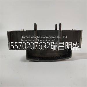
Module spare parts TRICONEX 2000417
Product Details
Product Details
Product Description
Product DescriptionFocus on DCS, PLC, robot control system and large servo system.
Main products: various modules / cards, controllers, touch screens, servo drivers.
Advantages: supply of imported original products, professional production parts,
Fast delivery, accurate delivery time,
The main brands include ABB Bailey, Ge / fuanc, Foxboro, Invensys Triconex, Bently, A-B Rockwell, Emerson, ovation, Motorola, xyvom, Honeywell, Rexroth, KUKA, Ni, Deif, Yokogawa, Woodward, Ryan, Schneider, Yaskawa, Moog, prosoft and other brands
| TRICONEX 2000417 |
For best results, the cutoff frequency of a particular filter should remain within this range. If the cutoff frequency goes above this range, the prefilters and postfilters interfere with signals in the passband, causing additional attenuation near the cutoff frequency. If the cutoff frequency goes below this range, the level of protection from aliasing within the filter and from imaging in the output decreases. DC-Correction Circuitry and Overload Recovery The SCXI-1141/1142/1143 module incorporates circuitry that corrects for the DC gain and offset errors of the filters, leaving only the errors of the amplifiers. However, this correction circuitry takes approximately 15 s to completely respond to changes in these errors due to overload conditions (caused by driving the output signal outside of the ±5 V range) and upon power-up (no data should be taken during the first 15 s). Overload conditions result whenever the input signal exceeds ±5 V/gain. You must use a gain setting that prevents the maximum input signal from exceeding this limit, or the DC-correction circuitry will take 15 s to recover from overloads. Table 4-1. Cutoff Frequency Ranges for the SCXI-1141/1142/1143 Module Prefilters and Postfilters Range Cutoff Frequencies A 10–25 kHz B 4.3–10 kHz C 1.9–4.4 kHz D 1.5–3.4 kHz E 700 Hz–1.8 kHz F 300–700 Hz G 130–300 Hz H 100–225 Hz I 49–110 Hz J 21–49 Hz K 15–21 Hz L 10–15 Hz Chapter 4 Theory of Operation SCXI-1141/1142/1143 User Manual 4-16 Filter Bypass Mode You can bypass the filter of any channel through software control, thus making the unfiltered signal available at the output. The input amplifiers are not bypassed. You can use the filter bypass to examine the effect that the filter has on the input signal. Using this mode, you can examine an input signal without the added effects of passband ripple and phase nonlinearities. At power-up and at reset, all the channels of the SCXI-1141/1142/1143 module default to the filter bypass mode. Rear Connector Analog Outputs The connector signals A OUT and A GND are the outputs of channels 1 through 7. You can configure the OUTPUT and OUTPUT REF signals as any channel (0 through 7) of the SCXI-1141/1142/1143 module or as the output of a channel passed along the SCXIbus from any other module in the chassis. Thus, the SCXI-1141/1142/1143 modules can present its outputs in both parallel and multiplexed modes. Multiplexed Mode (Recommended) In multiplexed mode, the output signals for channels 1 through 7 are sent to the rear signal connector but are usually ignored. All samples from the module are from the OUTPUT signal of the rear signal connector, which you can configure as the output of any channel of the SCXI-1141/1142/1143 module or as the output of any other module in multiplexed mode that is sending its output onto the SCXIbus. You can also configure the SCXI-1141/1142/1143 module to send any one of its outputs to the SCXIbus. Thus, in multiplexed mode only, one module in a chassis needs to be connected to a DAQ device. You can pass signals from the other modules to the DAQ device through the SCXIbus.
>> New Design 2022 Custom Logo Wholesale Mask Manufacturing Machine Kf94
>> 16m Alloy Landing Craft for Island Transport Cargo Transport Aluminum Landing Craft for Sale
>> China Supplier Good Price Ultrasonic Welding Machine
>> Low Price Original HC-06 RF Wireless BT Transceiver Slave Module
>> Cheap Lightweight Level 5 Cut Resistant Gloves for Industrial Safety Work
>> JIMBO High quality cheap security front loading steel electronic digital iron cash drop depository safe
>> High Quality and Best Price Photoluminous/Luminescent/Luminous/Glow in The Dark/Noctilucent/Photoluminescent/Night Glow Pigment
>> Fully Automatic Fish Food Production Line Fish Feed Machinery Ornamental Fish Feed Processing Line
>> Reliable Xiaomo Wang Electric Bicycle Featuring Lead Acid Power Ebike E-Bike
>> Military Grade Nij Iiia School Bulletproof Backpack with USB Charging Port
>> Bead Mill, Versatile Mill for Paints and Coatings
>> Self-Pressurized Liquid Nitrogen Tank of Scientific Research Test 150L
>> Portable 4kw 6HP High Prefermance Variable Speed Oil Injected Direct Screw Air Compressor with Tank
>> Indoor GJFJV Tight 2.0mm/3.0mm Sc/LC/St/FC Patch Cords and Pigtails
>> Cheapest Fash Express Delivery DHL/UPS/EMS/FedEx Door to Door Shipping From China to Worldwide
>> Universal Milling Machine Heavy Duty and Milling Machine X5040 Hot Sale
>> Horizontal metalworking Lathe Machine Cp6166L/Cp6266L, Universal Horizontal Gap Bed Type
>> Bl-V7 Metal-Cutting Tools Blin China Machining Fanuc CNC Milling Machine with Cheap Price
>> Souvenirs Personal Decorations Leon Metal Gift Hard Enamel Pins Pin Badge
>> Half Cover Automatic Hydraulic Metal Surface Grinding Machine Sga401000ah Sga401000ahr Sga40100ahd
>> Indoor Billiard Table Pool Table for Sale
>> Android 10 Chainway OEM C72 IP65 4G UHF RFID Reader for Warehouse 1d/2D Barcode Scanner 865-868MHz / 920-925MHz / 902-928mh
>> Professional Gantry CNC Milling Machine for Milling Boring Drilling Automotive Mold (CKM2516)
>> High Quality Disposable Medical Soft Pvc Nebulizer With Mouth Piece
>> Brand Fashion SKMEI 9241 Top Luxury Stainless Steel Strap Fashion Mens Stopwatch Wristwatch
>> Wholesales Multi Widths Gold Foil Gift Package Party Decoration Grosgrain Ribbon Christmas Ribbon for Festival
>> ERW Tube Mill for Efficient Round and Square Metal Tube Forming
>> Top Brand Invt 2kw Solar Inverter on Grid Single Phase
>> 27m3 Construction Equipment Stainless Steel Tank /Storage Bins
>> M7140 Metal Surface Grinding Machine for Sale From China Factory