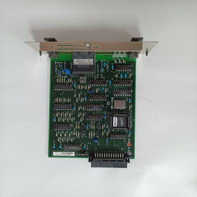
AIP591
Product Details
Product Details
Product Description
Product DescriptionBrand: YOKOGAWA
Type:AIP591
Origin: the United States
Warranty: 365 days
Colour: new/used
Shipping method: Courier delivery
Module of PLC, DCS, ESD system card, the card is a vibration monitoring system, steam turbine control system module, the advantages of the gas generator spare parts brand: Allen Bradley, BentlyNevada, ABB, Emerson Ovation, Honeywell DCS, Rockwell ICS Triplex, FOXBORO, Schneider PLC, GE Fanuc, Motorola, HIMA, TRICONEX, Prosoft etc. Various kinds of imported industrial parts of our products are widely used in metallurgy, petroleum, glass, aluminum manufacturing, petrochemical industry, coal mine, papermaking, printing, textile printing and dyeing, mechanical, electronic manufacturing, automobile manufacturing, plastic machinery, electric power, water conservancy, water treatment/environmental protection, boiler heating, energy, power transmission and distribution and so on.
SPECIFICATIONS NOTE Unless otherwise specified, the specifications are worse-case limits and apply over the specified operating ambient temperature and over the specified operating line voltage.
Peak Output Current listed is for sine mode. In six-step mode, the peak output currents are scaled to give the same output torque as in sine mode with a pure sinusoidal Back EMF motor. To convert ARMS to A(0-pk), multiply ARMS * 1.414. 2 For intermediate ambient temperatures linearly derate between adjacent provided 0-30o C, 40o C, or 50o C ratings. At higher ambient temperatures (above 30o C) the mounting surface temperature must be thermally conductive enough to limit the mounting temperature to less than 75o C. 3 Single phase operation of the S20660, S21260, S2460 requires derating of continuous output power to avoid excessive ac line front end currents. 4 See Manual Appendix for voltage loss vs cable length. 5 Total drive dissipation = power stage dissipation + control power. Control power adder is: Base unit only = 7W Base plus option card = 10W 6 For 120 Vac voltage doubled operation of S20250, S20350 units see Appendix D for power specifications
QUICK START GUIDES There are two types of Quick Start Guides depending on the Communication Mode of the drive. If you are not using an S200 Base Unit Drive (no SynqNet Option Card), follow the S200 Base Unit Drive Quick Start Guide. If you are using an S200 SynqNet Drive, follow the S200 SynqNet Drive Quick Start Guide. 4.1 S200 BASE UNIT DRIVE This Quick Start Guide is designed to help a user quickly setup one of the following S200 Drives. See Drive Model Numbers and Descriptions for a complete list of S200 drives. • S20330-VTS, S20630-VTS, S20260-VTS, S20360-VTS, S20250-VTS, S20350- VTS The setup consists of the following steps: 1. S200 Tools Software Installation 2. Hardware Setup 3. S200 Tools Communication Wizard 4. Motor Feedback Configuration
5. Save Options 4.1.1 S200 Tools Software Installation Follow the installation instructions from the CD-ROM or zip file. S200 Tools supports the following Operating Systems: • Windows 2003 Server • Windows XP, All Service Packs – (SP) • Windows 2000, SP2 • Windows XP embedded • Windows NT4, SP6 4.1.2 Hardware Setup 4.1.2.1. DRIVE SETUP Connect a serial communication cable between the drive and host computer to establish a communication link between the host computer and the S200 Base Unit drive. 1. Plug one end of a serial communications cable to J5 (Serial Port) of the S200 drive and the other end of the cable to the host computer's serial COM port. NOTE: The serial communications cable is not shipped with the drive. It must be ordered separately.
>> 2330 Best Wedding Dress Sweetheart Neckline Wedding Bridal Dress with Detachable Sleeve Bridal Wedding Dress with Princess Skirt 2024 New Dress
>> High quality Mini Mobile gold screening machine system for Sell
>> Custom Memo Pad Reminder Notebook to Do List Notepad with Gold Foil Logo Note Book Printing
>> Cheap and Safe Logistics Companies for Sea and Air Freight, Shipping Companies, UPS, DHL, FedEx, International Logistics, From China to Saudi Arabia Logistics
>> Factory Directly Sell F. C 98.5% S 0.5% Low Sulfur Calcined Petroleum Coke with Best Price
>> Kid Game Playground Training Equipment Swing Monkey Bar Handles Durable Safety Ratchet Slackline Set Kids Obstacle Course
>> Crack Width Gauge/Crack Measuring Device for Concrete
>> Factory Supply Aluminum 16" Manhole Cover 460 for Fuel Tanker Truck
>> 12ton Plastic Oil Making Plant by Pyrolysis Zero Pollution
>> Huafon Wholesale Microfiber PU Leather Suede Fabric Sofa Cover Shoe Lining Garment Bag Fabric Manufacuturer
>> Men's Custom Sublimation Blue and White Jacket with Blue Zipper
>> Jinnfa Small CNC Machine to Produce Different Metal Parts with High Precisions
>> Branch Light with LED (ZT1005)
>> Blin Plywood Case/Steel Pallet Drilling Machine CNC Vertical Machining Center with CE
>> Hsg Laser Plates and Pipes Fiber Laser Cutting Machine 1500W 2000W 3000W CNC Stainless Steel/Carbon Steel Aluminium Sheet Metal Fiber Laser Cutting Tube Machine
>> Hot Sales Glass Cover Roll Top Bread Bin Stainless Steel Bread box
>> 500kg/H 1000kg/H Complete Animal Feed Pellet Machine, Pellet Cooler Packaging Machine, Cattle Pig Poultry Production Mill Line
>> NIBOSI 2553 Wholesale Fashion Mens Watch Top Luxury Outdoor Men Wristwatch Casual Male Quartz Watch Relogio
>> Classy Performing NPK compound fertilizer granulation equipment With Low Energy Consumption
>> CNC Tower Angle High Speed Drilling Cutting Marking Machine
>> Cost-Effective Baby Anti-Fall Pillow Children Learning Walk Anti-Collision Protection Pad
>> 15 Axis Automatic Lanhao Panel Bender China CNC Bending Machine
>> After Market Auto Engine Parts Timing Chain Kit for MAZDA R2AA R2BF TK7090-6
>> Rsm955 Best Quality Alloy Rim Straighten Machine Wheel Repair Machine
>> 11 Inch Dual Motor 72V 7000W 2 Wheels 100kph Folding Electric E Kick Scooter for Adult
>> Factory Price Black & White Copier for Konica Monica Bizhub 754 654 754e 654e
>> 550W Mono Crystalline Solar PV Panel
>> Sport Toy Deformation Soft Bullet Gun Shooting Game for Kids
>> Qt8-15 Automatic Concrete Block Making Machine Building Block Machine
>> Single Phase High Voltage 35kv Floor Mounted No Fuse Capacitor